This is the first in a series of posts about programming the Nordic Semiconductors nRF51822 Bluetooth low energy micro-controller using the Arduino IDE. The post is a big one as it describes the entire hardware and setup process.
The board I’m using can bought bought on eBay, AliExpress or Amazon for well under $10
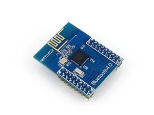
The board does not have either USB or an onboard serial based bootloader, so at least initially, it has to be programmed using an external SWD programmer.
I’m currently using a Maple Mini STM32 board as a programmer

By programming it with a custom version of the Black Magic Probe firmware (more on this later), but any SWD compatible programmer should be able to program this device, as long as the programmer explicitly supports the nRF51822 – One other programmer which I know works is the JLink by Segger.
The Maple Mini is available mainly through eBay and AliExpress for around $5 (http://www.ebay.com/sch/i.html?_from=R40&_trksid=p2050601.m570.l1313.TR0.TRC0.H0.Xmaple+mini+stm32.TRS0&_nkw=maple+mini+stm32&_sacat=0 ) and you will also need a USB to serial converter to program it, like this one
http://www.ebay.com/sch/i.html?_odkw=usb+serial+cp2102&_osacat=0&_from=R40&_trksid=p2045573.m570.l1313.TR0.TRC0.H0.Xusb+serial+6+pin.TRS0&_nkw=usb+serial+6+pin&_sacat=0 or any USB to serial that supports 3.3V devices.
Although not essential, its a lot easier to connect the nRF51822 RF module if you use a “Motherboard” like this one, which are also available on eBay and AliExpress etc, for around $12 (USD) (without the radio module)

The main reason that you should consider buying this board, is that the RF module, uses pin size and spacing which is not commonly used on other development boards, i.e the pins are not 0.1 inch apart, and the pins are shorter and thinner than used on Arduino shields etc.
However if you are happy to solder some wires to the module, you can save yourself at least $10, which is what I’ve done as I’m still waiting for my Motherboard to arrive.
Anyway, enough of the hardware you’ll need…
What software is required.
The first thing you’ll need, if you don’t already have it, is a copy of the Arduino IDE. Currently the only versions of the IDE that I’m supporting are 1.6.4 and 1.6.5
Once you have installed the Arduino IDE you need to add either the Arduino Due or Arduino Zero board using the Boards Manager. The reason this is currently required, is to install the ARM compiler and not for the actual Due or Zero. At a later date I will make a JSON file so that the nRF51822 can be installed without needing to install the Due, but at the moment this is the workaound you will need to use.
The next thing you need to do is download the third party core files from github https://github.com/rogerclarkmelbourne/nRF51822-Arduino/tree/S130_corelib, specifically this zip file https://codeload.github.com/rogerclarkmelbourne/nRF51822-Arduino/zip/S130_corelib
Next, go to your Arduino sketches folder and if there isn’t already a hardware folder, make a folder called hardware
Unzip it, and copy the RBL folder from inside /arduino-1.6.x/hardware into your newly created hardware folder, and restart the Arduino IDE
Now under the boards manager you will have a new board “Generic nRF51822”
Now to make yourself a SWD programmer from your Maple mini
First you will need to download the firmware from github https://raw.githubusercontent.com/rogerclarkmelbourne/blackmagic/master/binaries/blackmagic_maple_mini.bin
And also on Windows download the Flash Loader from STM http://www.st.com/st-web-ui/static/active/en/st_prod_software_internet/resource/technical/software/demo_and_example/stsw-mcu005.zip
Connect the USB Serial to the Maple mini by RX <–>TX and using GND and Vcc to GND and 3.3V on the USB to serial connector.
You also need to connect the Boot1 pin to gnd on the maple mini during programming
Then press and hold the button at the end of the Maple mini and then press and release the reset button (this will put it into serial upload mode)
Then use the STM Flash loader to upload the binary file to the Maple mini.
Once its been flashed, connect the Maple mini via its USB connector to your PC and it should be detected as 3 new USB devices.
On windows you will need to install the drivers for these, by downloading http://www.blacksphere.co.nz/downloads/bmp_driver_20130819.zip and unziping, then open the device manager and select each of the 3 unknown usb devices in turn and select update driver software, then browse to the folder you have just unziped and allow windows to install the drivers.
Note in the Windows device manager, which new USB device is shown as the GDB server, as you need to select that COM port number in the Arduino IDE to upload.
To connect the Maple mini to the nRF51822, you need to connect the following pins
For the SWD programming of the module use
Pin 6 -> SCLK on the nRF51822 or on the JTAG connector on the motherboard
Pin 7 -> SDO on the nRF51822 or on the JTAG connector on the motherboard
For USB to serial, you can use these pins on the Maple mini
Pin 8 -> P0.09
Pin 9 > P0.11
GND -> Gnd on the nRF51822 or Motherboard
You can use the USB to Serial that is on the Motherboard instead of the Maple mini, in which case don’t connect pins 8 and 9
If you are not using the motherboard or want to power everything from the Maple mini, you will also need to connect
Vdd to Vdd (either on the nRF51822 or the Motherboard)
Finally…
open an example sketch like Blink and upload, and if everything is working, you should see a LED blinking on the Motherboard.
If you won’t have a motherboard, you’ll need to connect a LED to pin P0.15, as this is currently the mapping that I’ve inherited from the RebBearLab files.


